

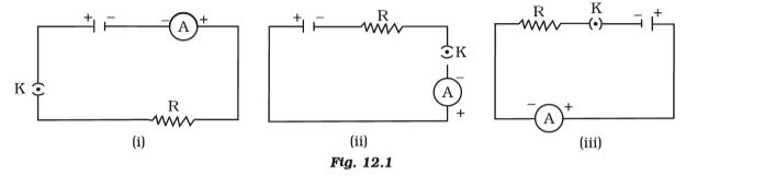
1. In the circuit diagrams of Figure 12, a cell, a resistor, a key, and an ammeter are arranged as shown. 1. The ammeter will record Soln as the current.
(a) maximum in case I
(b) maximum in case (ii)
(c) a maximum in case (iii)
(d) a maximum in all instances
1. In the circuit diagrams of Figure 12, a cell, a resistor, a key, and an ammeter are arranged as shown. 1. The ammeter will record Soln as the current.
(a) maximum in case I
(b) maximum in case (ii)
(c) a maximum in case (iii)
(d) a maximum in all instances
Explanation:
The answer (d) is the same in each case.
The current will be the same in each circuit because none of the circuits have changed, as explained.
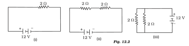
2. The circuits depicted in Figure 12.2 below will represent the heat produced in the resistor or combination of resistors connected to a 12 V battery.
(a) identical in every instance
(b) In the event (i)
(c) maximum in example (ii)
(d) maximum in instance (iii)
2. The circuits depicted in Figure 12.2 below will represent the heat produced in the resistor or combination of resistors connected to a 12 V battery.
(a) identical in every instance
(b) In the event (i)
(c) maximum in example (ii)
(d) maximum in instance (iii)
Explanation:
The appropriate response is (c) in case (ii)
Here, two transistors are linked in series. The total resistance will be less than the total of the individual resistances because they are connected in parallel in figure (iii). Because greater heat is produced by increased resistance, option c) is the proper reaction.
3. A metallic wire's electrical resistance is dependent on
(a) its length. (b) Its thickness (c) How it looks. (d) the material's nature
3. A metallic wire's electrical resistance is dependent on
(a) its length. (b) Its thickness (c) How it looks. (d) the material's nature
Explanation:
The nature of the substance is (d) as the response.
4. The filament of an electric bulb draws a current of 1 A. In 16 seconds, approximately how many electrons would flow through a cross-section of the filament?
(a) 1020 (b) 1016 (c) 1018 (d) 1023
4. The filament of an electric bulb draws a current of 1 A. In 16 seconds, approximately how many electrons would flow through a cross-section of the filament?
(a) 1020 (b) 1016 (c) 1018 (d) 1023
Explanation:
Answer is (a) 1020
Explanation:
I = Q/t
Q= It
Q= 1 x 16
Q= 16 q
Q=ne
n = Q/e
n = 16 /1.6 x 10-19
n = 10 x 1019
1020 electrons are in n.
1020 electrons are flowing at this time.
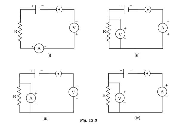
5. Determine the circuit (Figure 12.3) in which the electrical parts are correctly linked.
(a) (i) (b) (ii) (c) (iii) (d) (iv)
5. Determine the circuit (Figure 12.3) in which the electrical parts are correctly linked.
(a) (i) (b) (ii) (c) (iii) (d) (iv)
Explanation:
The answer is (b) (ii)
6. How much resistance can be created with a total of five 1/5 resistors?
(a) 1/5 Ω (b) 10 Ω (c) 5 Ω (d) 1 Ω
6. How much resistance can be created with a total of five 1/5 resistors?
(a) 1/5 Ω (b) 10 Ω (c) 5 Ω (d) 1 Ω
Explanation:
The response is (d) 1
When resistors are connected in series, the maximum resistance is achieved.
R= 1/5+1/5+1/5+1/5+1/5
= 5/5
= 1Ω
7. What is the smallest resistance that can be created using five 1/5 resistors?
(a) 1/5 Ω (b) 1/25 Ω (c) 1/10 Ω (d) 25 Ω
7. What is the smallest resistance that can be created using five 1/5 resistors?
(a) 1/5 Ω (b) 1/25 Ω (c) 1/10 Ω (d) 25 Ω
Explanation:
The solution is (b) 1/25
Explanation: When resistors are connected in parallel, the least resistance is produced.
1/R = 5 + 5 + 5 +5 +5= 25 Ω
R=1/25Ω
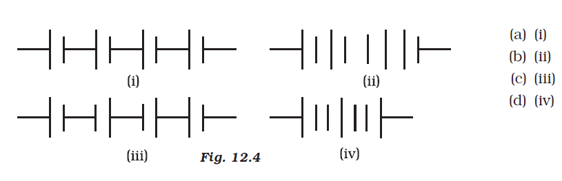
8. Soln is the correct illustration of the series of cell combinations that achieve their maximum potential (Figure 12.4).
(a) (i) (b) (ii) (c) (iii) (d) (iv)
8. Soln is the correct illustration of the series of cell combinations that achieve their maximum potential (Figure 12.4).
(a) (i) (b) (ii) (c) (iii) (d) (iv)
Explanation:
The answer is (a) (i)
Explain: In this instance, the positive terminal of the following cell is close to the negative terminal of the one before it.
9. Which of these best describes voltage?
(a) Workdone/current * times
(b) Work done × Charge
(c) Workdone * Time/ Current
(d) Work done × Charge × Time
9. Which of these best describes voltage?
(a) Workdone/current * times
(b) Work done × Charge
(c) Workdone * Time/ Current
(d) Work done × Charge × Time
Explanation:
(a) Workdone/current * times
10. A cylindrical conductor with a uniform cross-sectional area of A and length l has resistance R. A cross-sectional area of another conductor with length 2l and resistance R is present.
(a) A/2 (b) 3A/2 \s (c) 2A (d) 3A
10. A cylindrical conductor with a uniform cross-sectional area of A and length l has resistance R. A cross-sectional area of another conductor with length 2l and resistance R is present.
(a) A/2 (b) 3A/2 \s (c) 2A (d) 3A
Explanation:
The solution is (c) 2A.
P=
RA/l
Once Length has doubled
P=
RA/l/RA/l
= P=
RA/2l
A=2A
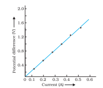
11. In an experiment, a student plots the V-I graph for three samples of nichrome wire with the matching resistances R1, R2, and R3 (Figure.12.5). Which of these is true?
(a) R1 = R2 = R3
(b) R1 > R2 > R3
(c) R3 > R2 > R1
(d) R2 > R3 > R1
11. In an experiment, a student plots the V-I graph for three samples of nichrome wire with the matching resistances R1, R2, and R3 (Figure.12.5). Which of these is true?
(a) R1 = R2 = R3
(b) R1 > R2 > R3
(c) R3 > R2 > R1
(d) R2 > R3 > R1
Explanation:
The appropriate reaction is (c) R3 > R2 > R1
Reason: Current flow and resistance are inversely related. The largest resistance will show less current flow, hence the correct answer is C.
12. When the temperature remains constant, increasing the current I through a resistor by 100% will cause the power dissipation to increase by
(a) 100%s (b) 200%s (c) 300% (d) 400%.
12. When the temperature remains constant, increasing the current I through a resistor by 100% will cause the power dissipation to increase by
(a) 100%s (b) 200%s (c) 300% (d) 400%.
Explanation:
300% of (c) is the answer.
Explain: The square of the current is inversely associated with the quantity of heat generated by a resistor. Hence, when the current doubles, the heat loss will increase by 2 to equal 4. There will be a 300% increase as a result.
13. The resistivity does not change.
(A) The information has been changed
(b) a shift in temperature (c) a change in the resistor's shape.
(d) variations in material and temperature
13. The resistivity does not change.
(A) The information has been changed
(b) a shift in temperature (c) a change in the resistor's shape.
(d) variations in material and temperature
Explanation:
The right answer is (c) the resistor's shape has changed.
14. In an electrical circuit, three incandescent bulbs are linked in parallel to an electric supply with respective wattages of 40 W, 60 W, and 100 W. Which of the following possibilities regarding their brightness is most probable?
The brightness of each bulb will be the same.
(b) Bulb A will have the brightest illumination.
(c) The brightness of bulb B will surpass that of bulb A.
(d) The brightness of bulb C will be less than that of bulb B.
Explanation:
Because bulb B will shine brighter than bulb A, the correct response is (c).
15. In a circuit of electricity, a 6 V battery is connected in series with two resistors of 2 and 4 ohms, respectively. The 4 resistor will produce heat for 5 seconds.
(a) 5 J (b) 10 J (c) 20 J (d) 30 J
15. In a circuit of electricity, a 6 V battery is connected in series with two resistors of 2 and 4 ohms, respectively. The 4 resistor will produce heat for 5 seconds.
(a) 5 J (b) 10 J (c) 20 J (d) 30 J
Explanation:
(c) 20 J Soln
Reason : R = 4+2 = 6 is the equivalent resistance of the circuit.
The heat dissipation formula for a 4-ohm resistor is H = I2Rt = 20J for current I= V/R = 6/6= 1A.
16. An electric kettle consumes 1 kW of power when operated at 220 V. What fuse wire rating should be used for it?
(a) One (1), Two (2), and Four (4) (d) 5 A
16. An electric kettle consumes 1 kW of power when operated at 220 V. What fuse wire rating should be used for it?
(a) One (1), Two (2), and Four (4) (d) 5 A
Explanation:
(d) 5 A is the answer.
Reason:
P=V x I
Moreover, 1000 w = 220 v x I I =1000 w/220 v = 4.54 A s = 5 A
17. Two resistance resistors are present. The numbers 2 and 4 will have the following properties when linked to a battery:
(a) When connected in parallel, they share the same current.
(b) the same current runs through them when they are linked in series.
(C) They have the same potential difference when connected in a series.
(d) a special P
Explanation:
The right answer is (b): The same current passes through them when connected in series.
Explanation: There are no branches to the current because the resistor receives a common current in a series configuration.
18. There are also more ways to express an electric power unit
(a) volt-ampere (b) kilowatt-hour (c) Watt-second (d) and joule-second
18. There are also more ways to express an electric power unit
(a) volt-ampere (b) kilowatt-hour (c) Watt-second (d) and joule-second
Explanation:
The appropriate response is (a) V/A.
Explain: Volt-amperes are used to measure the apparent power of electrical circuits (VA). The letters Ws or W.s stand for watt-second, a derived unit of energy equivalent to the joule. In joules-seconds, Planck's constant is expressed.
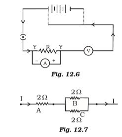
19. To understand about Ohm's law, a young child drew the electrical circuit in Figure 12.6. He should correct the circuit diagram, his tutor said. Examine the circuit diagram, make all the necessary corrections, and then rewrite it.
19. To understand about Ohm's law, a young child drew the electrical circuit in Figure 12.6. He should correct the circuit diagram, his tutor said. Examine the circuit diagram, make all the necessary corrections, and then rewrite it.
Explanation:
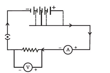
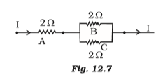
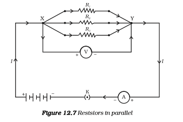
20. As shown in Figure 12.7, A, B, and C, three 2 resistors, are linked. They each experience energy loss and can only withstand 18W of electricity before melting. Determine the maximum current that can flow through the three resistors.
20. As shown in Figure 12.7, A, B, and C, three 2 resistors, are linked. They each experience energy loss and can only withstand 18W of electricity before melting. Determine the maximum current that can flow through the three resistors.
Explanation:
Current P= I2R 18W = I2 times I2, or 18W/ 2s = 9sI, or 3A.
Three times as much current as usual can flow through A.
Equal to current through C times half of current through A is current through B.
Current through B is equal to 1/2 x 3 current through C, which is 1.5 A, and current through B.
21. Low or high resistance should be used in an ammeter? give a reason.
21. Low or high resistance should be used in an ammeter? give a reason.
Explanation:
An ammeter's resistance should be zero because it shouldn't obstruct the flow of electricity.
22. Draw a circuit diagram for an electrical system that consists of a cell, a key, an ammeter, two parallel sets of four resistors, two series sets of two resistors, and a voltmeter that is linked across the parallel pair. Will the potential difference across the four-ohm parallel setup and the two-ohm resistor have the same value? give a reason.
22. Draw a circuit diagram for an electrical system that consists of a cell, a key, an ammeter, two parallel sets of four resistors, two series sets of two resistors, and a voltmeter that is linked across the parallel pair. Will the potential difference across the four-ohm parallel setup and the two-ohm resistor have the same value? give a reason.
Explanation:
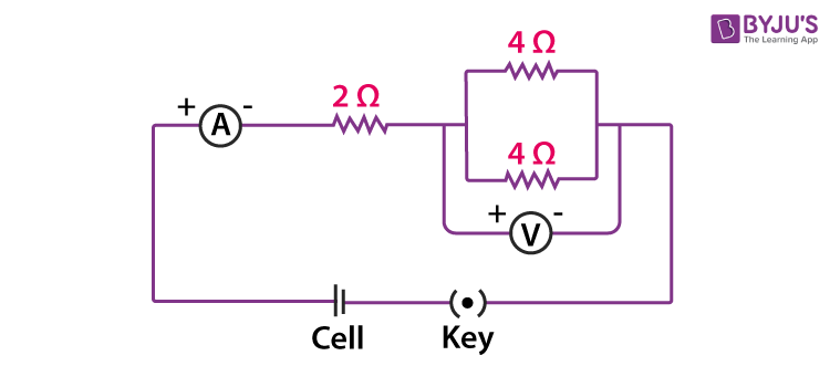
The following formula can be used to calculate the total resistance for a parallel arrangement of 40 resistors:
1/R = 1/4+1/4 = 1/2 \sR= 2 Ω
As a result, a parallel combination's resistance is equal to a series of resistors' resistance. Hence, the potential difference between the 20 resistance and the other two parallel-connected resistors will be equal.
23. How is the safety of electrical equipment increased by employing a fuse wire?
23. How is the safety of electrical equipment increased by employing a fuse wire?
Explanation:
Fuse wire is more durable than main wiring, Soln. when the electric current is amplified substantially. Fuse wire melts, breaking the circuit. This prevents damage to electrical machinery.
24. Which electrical resistance ? A series electrical circuit that contains a resistor made of metallic wire and an ammeter measures 5 A. The ammeter reads half as the wire is doubled in length. Why?
24. Which electrical resistance ? A series electrical circuit that contains a resistor made of metallic wire and an ammeter measures 5 A. The ammeter reads half as the wire is doubled in length. Why?
Explanation:
The ability of a conductor to resist current flow is one of its characteristics. A given material has a certain resistance. Inversely correlated with current flow and correlated with conductor length is resistance.
As length doubles, resistance grows by twofold and current flow is reduced by half. This is why the ammeter reading has reduced.
25. What is the name of the energy supply for commercial use? Give it equivalents in joules.
25. What is the name of the energy supply for commercial use? Give it equivalents in joules.
Explanation:
A commercial electrical energy unit's name is kilowatt/hr.
Every kilowatt-hour, 1000 W divided by 60 seconds = 3.6 106 J.
26. A series circuit made up of a conductor of 5 and an electric bulb produces a current of 1 amp when it is coupled to a 10 V battery. Find the resistance of the electric lamp. If a resistance of 10 is connected in parallel with this series combination, the current flowing through the five conductors and the potential difference across the bulb will change (if at all). give a reason.
26. A series circuit made up of a conductor of 5 and an electric bulb produces a current of 1 amp when it is coupled to a 10 V battery. Find the resistance of the electric lamp. If a resistance of 10 is connected in parallel with this series combination, the current flowing through the five conductors and the potential difference across the bulb will change (if at all). give a reason.
Explanation:
(1) Suppose that R is the resistance of the electric bulb. Total series resistance for a vapour lamp is 5 + R I = v/r 1 = 10/5+R R = 5 ohm
(2) 10 V across the conductor and lamp, and I R = 1 * 5 = 5 Volt.
27. What are the benefits of using parallel wire arrangements in home wiring?
27. What are the benefits of using parallel wire arrangements in home wiring?
Explanation:
Due to the fact that it provides the same potential difference for all electrical equipment, domestic wiring is set up in parallel.
28. The ammeter A registers a current of 3A when all three lights are turned on and three identical bulbs, designated B1, B2, and B3, are connected as illustrated in Figure 12.8.
(i) What happens to the light from the other two bulbs when bulb B1 burns out?
(ii) What happens when the readings from bulbs A1, A2, A3, and A get fused to bulb B2?
(iii) How much power is lost in the circuit when all three bulbs are on at once?
Explanation:
(i) Potential differences are not divided in parallel circuits. Hence, if bulb one burns out, the other lights will continue to glow normally.
(ii) Ammeter A shows a reading of 3A. This shows that the Al, A2, and A3 have IA readings on all three.
(iii) R= V/I = 4.5V/3A = 1.5
P = I2R. = (3A)2 x 1.5 = 13.5 Ws at the moment.
29. Three 100 W incandescent lights are linked in series on an electrical circuit. The same source is connected in parallel by a different circuit's three lights with the same wattage.
(a) Will the brightness of the bulb be the same in both circuits? Describe your reaction.
(b) Then, in step (b), allow one bulb in each circuit to fuse. What happens to the remaining lights in each circuit? give a reason.
Explanation:
A series of bulbs will have three times the resistance of a single bulb. It follows that the current in the series combination will be one-third less than the current passing through each bulb in a parallel combination. Brighter light will be produced via parallel-connected bulbs.
The series-connected lights will quit glowing after the circuit has been broken and the current is zero. The parallelly connected bulbs must, nonetheless, maintain a constant brightness.
30. What is the Ohm's law, exactly? How can it be tested experimentally? Does it hold up under all conditions? Comment.
30. What is the Ohm's law, exactly? How can it be tested experimentally? Does it hold up under all conditions? Comment.
Explanation:
According to Ohm's law, the current flowing through an ideal conductor at constant temperature is inversely associated with the potential difference (voltage) across it.
Ohm's law demonstration using V/I = R
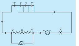
Make the circuit shown in Fig., which consists of four 1.5 V cells, an ammeter, a voltmeter, and a nichrome wire with a length of XY, let's say 0.5 m. (The alloy known as nicchrome is composed of the metals nickel, chromium, manganese, and iron.)
As a starting point, power the circuit with just one cell. Note the readings from the voltmeter (V) for the potential difference across the nichrome wire XY in the circuit and the readings from the ammeter (I) for current. Add them to the corresponding table.
The next step is to connect two batteries to the circuit. After that, record the ammeter and voltmeter readings for the circuit's measurements of the current flowing through the nichrome wire and the potential difference across the wire.Before using four cells, first use three cells in the circuit.
Repeat the procedure above using three cells in the circuit first, then four cells, and so on for each group of cells.
31. What does a substance's electrical resistivity mean, exactly? Who or what uses the unit? Describe an experiment to find out what factors affect conducting wire resistance.
31. What does a substance's electrical resistivity mean, exactly? Who or what uses the unit? Describe an experiment to find out what factors affect conducting wire resistance.
Explanation:
Resistivity is the inherent property of a conductor to resist the flow of electric current. The degree of resistance varies depending on the substance. The unit of resistance is m, or m.
Investigate the factors that influence conducting wire resistance by doing an experiment.
You'll also need some connecting wires, a nichrome wire, a torch, a 10 W bulb, an ammeter (0-5 A range), and a plug key.
Assemble the circuit by joining the ammeter and four 1.5 V dry batteries in series, leaving a gap XY in the circuit, as illustrated in Fig. 12.4.
Observation: The composition of the conductor is shown to affect resistance.
The length of the conductor affects resistance.
Cross-sectional area affects resistance.
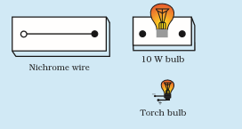
The circuit is finished by inserting the nichrome wire into the XY gap. Put in the key. It is important to record the ammeter reading. Take the key out of the plug. [Note: Always take the key out of the plug after measuring the circuit's current flow.]
The torch bulb should be used in place of the nichrome wire in the circuit, and the ammeter measurement should be used to calculate the current flowing through it.
The previous procedure should be repeated with the 10 W bulb in the XY gap. Do the ammeter values for the several components connected in the gap XY vary? What do the aforementioned findings imply?
You can carry out this action again by leaving any kind of tangible component in the space. Observe the ammeter readings in each circumstance. Examine the results.
32. Using an experiment, how can you prove that the same current travels through every part of the circuit made up of three resistances linked in series to a battery?
32. Using an experiment, how can you prove that the same current travels through every part of the circuit made up of three resistances linked in series to a battery?
Explanation:
Connect R1, R2, and R3 in series with each other to complete the circuit.
Use an ammeter to view the fluctuations in the current flow.
R1 is removed, and the potential difference between R2 and R3 is then measured.
To determine the potential difference between R1 and R3, remove R2 from the
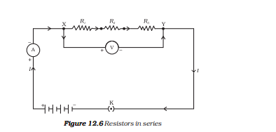
Observation: Because the ammeter reading was the same in each instance, it may be concluded that the circuit's current is constant.
33. How will you know if a battery and three parallel-connected resistors have the same potential difference (voltage)?
33. How will you know if a battery and three parallel-connected resistors have the same potential difference (voltage)?
Explanation:
R1, R2, and R3 should be connected in parallel to construct the circuit shown in the diagram.
Using a voltmeter, measure the potential difference between three parallel-connected resistors.
Consider the potential difference of the remaining resistor combination after resistor R1 has been removed.
After resistor R2 has been removed, measure the remaining resistance's potential difference.
Observation: The identical Voltmeter reading in each case shows that the potential difference between the three parallel-connected resistors is the same. To make sure, we can put up an ammeter in numerous places and monitor the current flow.
34. What does a Joule's heating impact look like? How can it be demonstrated experimentally? Describe its four real-world uses.
34. What does a Joule's heating impact look like? How can it be demonstrated experimentally? Describe its four real-world uses.
Explanation:
The amount of heat that a resistor can contain for the given resistance is precisely proportional to the square of the current, according to Joules.
Directly proportional to resistance for a given current and precisely proportional to how long the current is flowing through the resistor.
H = I2Rt applies to this.
Electrical current is denoted by I, resistance by R, and time by t. The heating effect is H.
showing the Joules law of heating
Take an immersion heater rod, and fasten it to a socket with a regulator connected.
It's important to remember that a regulator controls how much current passes through a device.
Measure how long it takes the immersion rod to heat a certain amount of water by putting the regulator's pointer to the lowest setting.
The regulator's pointer should be raised to the next level. When using an immersion rod, time the same amount of water as it is heating.
Repeat the preceding method for higher regulator levels to keep track of the time.
It is noticed that using a higher electric current results in faster heating of the same volume of water. This demonstrates the heating law of Joule.
Application:
The leafing effect of the current is used to power electric appliances like toasters, ovens, kettles, and heaters.
35. Determine the following in the electrical circuit depicted in Figure 12.9: 35.
(a) The combined effective resistance of the two 8 resistors
(a) Current going via a 4 resistor
(c) the potential for change over a 4-ohm resistance
(d) A 4-ohm resistor loses power
(e) Any variations in the ammeter readings
Explanation: